Checking Pipe Flexibility (ASME B31.3)
- ASME B31.3 offers a simplified formula for determining if a pipe section requires stress analysis; by analysis is meant a total pipe stress analysis such as would be provided by pipe stress analysis program.
- The ASME test formula is relatively simple and provides a quick check of pipe stresses. It does not provide stress values but does tell us if the pipe line might be in trouble from expansion stresses. Remember expansion can be negative and still be a problem.
- The formula is:

- K = test value and if less than 0.03 using the following dimensions the pipe routing does not require formal stress analysis under normal conditions
- D = Nominal pipe diameter (2 inch pipe is input as 2 inches)
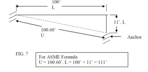
- y = total expansion [Δx] in inches from the equation below (Δx = α . L . ΔT) , this is expansion between the anchors as if the pipe ran straight from anchor to anchor
- U = total straight line length between anchors, feet
- L = actual length of pipe including elbows etc, feet
Example Solution :

T1 : 70 F
T2 : 250 F
Pipe Material : Steel
First step is to calculate Δx Expansion

In that equation “L” is selected as critical pipe length that one side is unsupported. Total expansion of this pipe is 1.402″.Now we will check if this piping system’s flexibility can absorb this expansion with ASME B31.3 Quick Check Formula.
- Note that “U” has become the hypotenuse of the triangle formed by the two straight legs.
- This is the straight line distance between anchors.
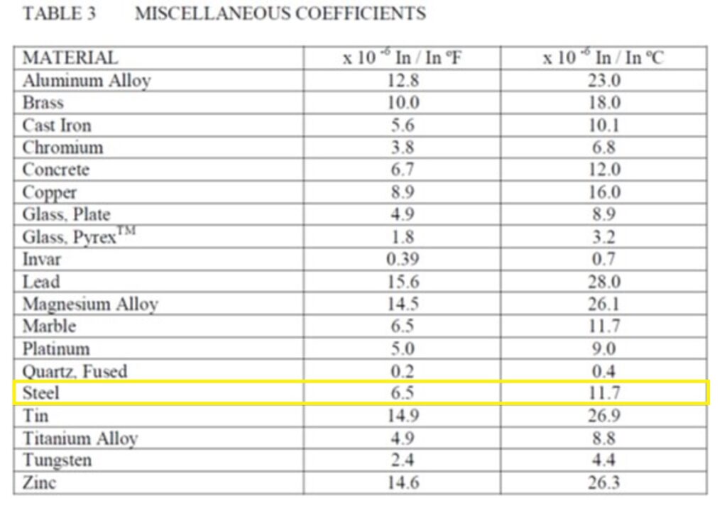
- Δx = 6.49 x 10^-6 in/in°F ( From TABLE 3) x 1207.2 in (100.6 FEET) x 180 °F = 1.41 in.
- Substituting in the formula
- K = Dy / (L-U)2
- D = Nominal pipe diameter, 2 inches
- K = test value and if less than 0.03 is acceptable
- y = 1.41 inches
- U = 100.6 feet
- L = 111 feet
- K = 2 in x 1.41 in / (111 ft. –100.6 ft.)2 = 0.026 in2 / ft. 2
- This indicates that the short section of downward turned pipe reduces the overall stresses
- to an acceptable level. Our length ration is 111 / 100 = 1.11 which is also acceptable.


